IMAR-3 PC-KEYBOARD
ADAPTER FOR SPECTRUM
(C) Droy 2002
This adapter, developed for me has the name IMAR-3 and his article
give all information to be constructed by electronic amateurs.
PC-Keyboard
adapter for Spectrum
What this
adapter do? Do I need to load something in my Spectrum?
This adapter is connected to expansion bus same as joysticks adapters, giving us the possibility of connecting an standard keyboard, type AT or PS/2. (Old keyboards 94-keys are unuseful). This heart of the adapter is a microcontroller PIC 16F84. This PIC should be programmed before insertion on the board ( a few steps forward will be explained how to program it). Once the PIC be programmed an inserted, is ready for working, and you don't need to open nor load anything in your Spectrum. .
If you opened your Spectrum sometime, you found two flat cables, 8 and 5 contacts which are part of bottom of keyboard, a matrix under rubber keys. The matrix is divided in 8 half-rows with 5 keys each. The following figure shows this:
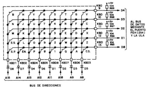
As you can see in the figure, every half-row is connected to one line in the upper-half of ADDRESS BUS, and the other end of every key is tied in a five-group to a line of DATA BUS, D0 to D4, through the ULA. When a key is pressed, the whole half-row is read (5 keys) and the I/O port writes a '0' in the address line of this half-row. For clarify: Let's assume that we want to know if is press the key 'W'. Then we read the port IN (64510)binary is 11111011 11111110. This reading set to '0' the line A0, telling to ULA that the keyboard is being read, and also the line A10 is set to '0', meaning that half-row number 2 is being read. In response, a number will be set, which binary bits are tied ,from D0 to D4 with keys 'QWERT' one to one, because DATA BUS is forced to '1' throu resistors R65-R69. (one key released means '1' and if pressed, is set to '0', got from address bus).
In this example, is the bit D1 which shows the status of key 'W'. You can see this 'online' writing following program and see the changing status depending the key you press in the half-row 'QWERT'. If the value is set to binary, is more clear to understand. In a emulator works fine, indeed!.
10 REM example of read of keys without command INKEY$20 CLS 30 PRINT AT 10,1;Byte read in half-row 2:;IN(64510)
40 GOTO 300
In the Spectrum, his keyboard is part of inner
hardware. PC-keyboards does not: is independient of the host. You can see
that only 4-wires cable is enought to communicate them. The host is tipically
a PC, but in our case is the controller which does the host role. Communication
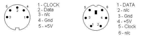
beetween PC and keyboard is done using a 5-pin DIN connector 180º
or using a connector PS/2 (mini-din 6-pin). In both cases one wire is the
'clock' signal, other wire is 'data' and the other two wires are power
supply +5V and GND.
LSB: Less Significative Bit
Scan code set 1: Is used for keyboards type XT 83-keys
Scan code set 2: The most common: used for keyboards 102-keys
Scan code set 3: Used only in PS/2 keyboards The Scan code set 1 is out of use.
The Scan code set 3 is the one which allows easily be used in this adapter, reason by is the choice. In order to use also older keyboards, I wrote another program shorter (less key functions as erase,escape,colon, etc) but can be used in keyboards type AT, Scan code set 2. In addition to Scan code set, keyboards can be configured in work modes: Make: when a key is press, the scan code is sent, and after releasing none code is sent. Make/Break: when a key is press, the scan code is sent and after relasing, again a scan code is sent, with a releasing-code 'F0' leading. Typematic: When a key is press, the scan code is sent, and after a delay, is re-sent till the key is released. The AT-type keyboards allows the delay of self-repeating (typematic), but not everyone lets the non-typematic. The PS/2-type keyboards always allows both modes. Following is an extract of Scan code 3, used by the IMAR-3 adapter:
Much and best quality info abot keyboards in:
http://panda.cs.ndsu.edu/~achapwes/PICmicro/keyboard/atkeyboard
The memory chip RAM 6116 is used to store in its first 8 cells the status of every 8 hal-rows, so, when Spectrum wants to read one of them, the adapter brings the content of the address in RAM where this status is stored: In this way, Spectrum 'believes' that are its own keys that are being pressed. When we pressa key, PIC gets his ScanCode.
Then, looks in his internal EEprom, where are previously loaded the codes por each ScanCode linked to each Spectrum' key and if the 'compare' is found, means thay keystroke is right. From memory address where ScanCode is, data for Key and for Half-row are developed. Once this value is calculated, program check if in port RA4 the controller is trying to read the keyboard. If answer is 'not', this access is blocked through port RA2 while the new status of the half-row is written in the address associated in RAM of controller. When Spectrum reads a half-row, uses a machine instruction IN A,(FE). This one activates (set the signal to 'low' level) for lines IORQ/RD and A0. Logic gates OR (parts of IC5A & IC5B) activates the transceiver (IC3 - 74LS245); after this, the spectrum can get data read from the RAM port (IC1-6116).
This means that when a half-row is bein read, the priority encoder
(IC7- 74LS148), do a code made of 3 address bits the number of the half-row
which is being read, and then, multiplexer quad two-entries (IC4 - 74LS157)
give access to spectrum's memory or in this controller to PIC which is
under logic control of IC5A , B , C and also by I/O port RA2 of PIC.
Spectrum |
Teclado PS/2 o AT
|
Symbol Shift |
Crtl (Left and Right)
|
Caps Shift |
Shift (Left and Right)
|
|
Caps Lock (Caps Shift + 2)
|
Caps Lock
|
|
Extended Mode (Caps Shift + Symbol Shift)
|
TAB (Edition mode only)
|
|
Cursor
|
Flechas del cursor (Edition mode only)
|
|
Backspace (Caps Shift + 0)
|
Borrar (Backspace)
|
|
Dot (.)
|
Dot (.) (Edition mode only)
|
|
Colon (,)
|
Colon (,) (Edition mode only)
|
|
Semicolon (;)
|
Semicolon (;) (Edition mode only)
|
|
C (")
|
Shift + 2 (Edition mode only)
|
|
Break (Caps Shift + Space)
|
ESC (Edition mode only)
|
You can choose betwen normal mode and edition mode pushing F12. The Joystick Interface II movement is mapped to the arrows keys, and fire button function to both Alt keys and the zero numeric. F1 will be very useful for PlusD and Disciple users.
F1 = LOAD d1;"snap "S
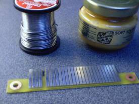
As stated in previous gadgets shown on 'Trastos de Droy', this controller can be made using preperfored boards in case you are not keen to use acid, developer, etc. I made this prototipe in this way because I could make some last minute changes during develpment instead of beguin again after each change. Given this design is finished, if you choice a Printed Circuit Board, is up to you the dessign, but can be useful to use EAGLE 4.0 and the scheme provided.
1. Pre-perfored boards.
As I use to do, a picture of all components before any soldering. If you never worked before with preperfored boards, in another section of 'Trastos de Droy' you'll find know how.
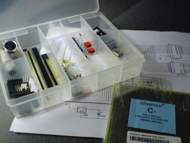
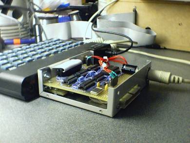
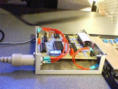
The basic is to arrange all components in the board and stick them with tape till I find the best way to inter-connection themselves. After a few tries, keeping in mind the extra holes for set apart the stripes, it looks like this picture:
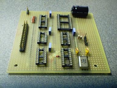
The 100nF capacitors are for electric noise reduction (generated for TTL technology), so they must be connected as near to power pines in each IC as you can. As is undesirable to forget any wire, I do the following: Upon the wires are being connected, I overwrite in red colour in the scheme to be sure that both ends of circuit are connected. Don't forget the power connections for IC's, because they usually aren't specified in schemes. Anyway, here you are the pinout:
|
Integrated Circuit
|
+5V
|
GND
|
|
75LS245
|
20
|
10
|
|
74LS157
|
16
|
8
|
|
74LS148
|
16
|
8
|
|
74LS32
|
14
|
7
|
|
PIC 16F84
|
15
|
5
|
|
6116
|
24
|
12
|
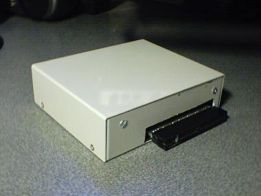
Little time after you have soldered all connections, and spent some time in doing the shape of box, this can looks so:
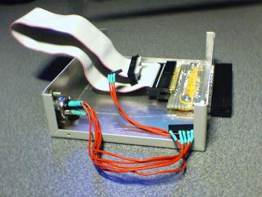
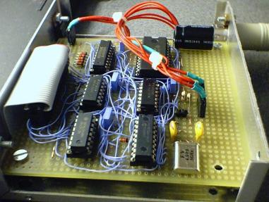
Little time after you have soldered all connections, and spent some time in doing the shape of box, this can looks so.
Pay attention about how the side of box is used
as heat sink of IC 7805, out of board. Don't worry because some components
of picture aren't the same as previous pictures: Is because the 'dynamic'
changes experienced along the making time. Anyway, the idea is to follow
the scheme of this ultimate version..
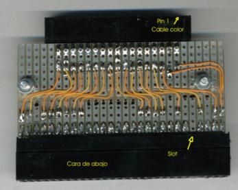
For multi-connection purposes through the flat
cable, I connect inside a 34-pin male connector to outside. See following
picture:

2. Using Printed Circuit Boards.
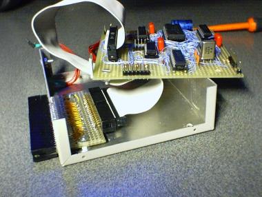
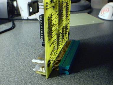
In this design, I looked for two targets: one is make its manufacturing as easy as possible, and the other is that expansion bus of the Spectrum can be propagated just in case you'll want to connect another more adapter in addition of IMAR-3. You'll have to use the photograpic method because the routes are really thin. If you are able to optimize this dessign, do it using Eagle, and if it works, will be published in this topic with your name and my aknowledgments.
As you can see at the bottom, the expansion bus is propagated using a small board that is soldered over the true pins of expansion connector. You need to do this board only in case of use of more adapters at a time. If other adapters has it's own propagate connections, this part can be avoided also. For the ones that prefers to add this part, a must is to tin-plate contacts. Is highly recommended to use ***¿FLUSHING PASTE?***. Don't forget to cut out the slot in the extension board.
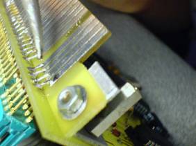
The voltage regulator LM7805 must be screwed on a heat sink. A tip:
in the aluminium workshops (windows, blinds, etc), they give to me for
free the small leftover parts, and here are use in double fuction: heat
sink and angle iron to stand the expnasion board. Next pictures illustrates
in detail the machining.
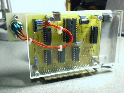
The front is covered using a fiberglass board (one that had cupper
but excessive acid turned it clean by mistake and so has a second life).
this material is cheap ans easy to use. The back is protected using clear
plastic. naturally that other materials can be used but the clear plastic
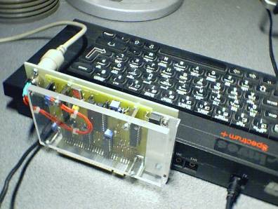
is a touch of class !!.
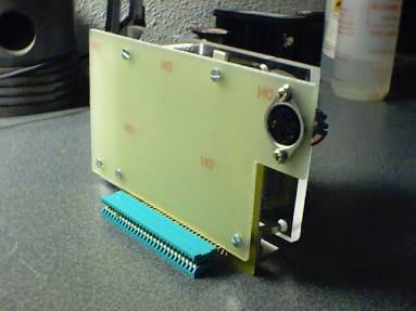
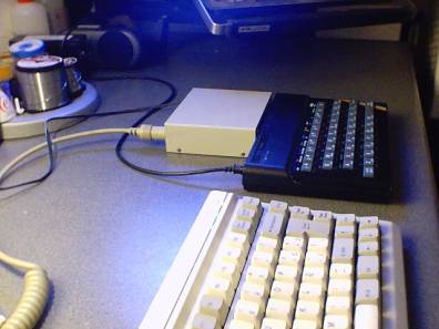
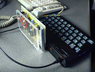
IMAR-3 proudly connected to an Spectrum 48K Plus.
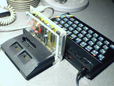
IMAR-3 assembled to an Spectrum 48K and to an clonic Interface II using bus propagate.
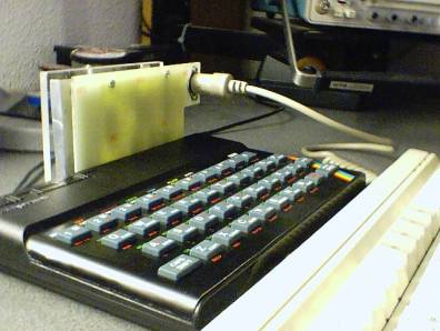
Front view: remark on thanks to the fact of side exit of keyboard is possible the assembly of several adapters, as well if IMAR-3 is the first, as is in another position, without being an obstacle .
Announcement for potentials buyers / purchasers:
Altought I'm not keen of selling adapters, I'll change some ot them by Spectrum's hardware. Strange as it may seem, after reading an article about Interface II' cartridges, I' don't have an authentic one. If you are prone to change it, just e-mail me. I just want hardware, preferably Sinclair, but nothing about tapes of programs.
3. PIC programmingThe family of microcontrollers PIC is one of the most used. Just a sight in the Web and you'll find heaps of info. You need write the program in the PIC. To accomplish this, you have to download in the 'dumps' section of this page the program or buy one; Aren't expensives: about 5 or 6 €, and then you have choices to program it:
Before aplying power for first time, it's a good idea to check all
the board before. Pay attention at key in the back connector of Spectrum
to avoid a shifted contact. Inmediately after power be on, all lights in
keyboard lit, then dark, and finally, Caps Lock will remain On. If this
happens, means that PIC is working fine. If unfortunately the sequence
is wrong, check the PIC connections, cause is the only IC doing the task
of keyboard initialization. You can remove the other IC's from it's sockets
to help the debugging. Before e-mailing me, be sure that all IC's have
the power connected (see above), is the most common failure. If you are
the proud owner of a oscilloscope, look for PIC clock pulses at pin 15-16.
Re-check solderings, point-to-point connections, keys of IC's. If after
a cute checking of all points it doesn't work, don't cut yourself the veins:
e-mail me, I can help.
After prototype was made I tried several trade programs to check quality: I expected to find only performance difference, because my PIC program wasn't still optimized. But... near a third of them had lacks of controllers. Even one of my favourites -Ultimate ¡ yes, the one of Knight Lore! - showed same problem. I had to diassemble this programs to study how his programmers did the keyboard reads.
TWIN READ OF TWO HALF-ROWS
KEYBOARD STATUS IN SINGLE READ
May I use a Xtal faster or slower than 4 MHz ?
No, the loops in the control program are calculated for 4 MHz, if you want to use a PIC with diferent speed, you has to compile the source again changing the speed field.
Do I have to use a DIN 5-pin connector or a Mini DIN 6-pin depending upon ver sion (AT or PS/2) of keyboard ?
The best is to use the connector keyboard type that you'll use commonly. It is possible to use the typical conversion plug. Altought is weird, there are PS/2 keyboards provided of DIN 5 connector.
Will the IMAR-3 implement new functions as 'shot autorepeat', 'joystick emulation', etc?
No. perhaps in the future i'll do improves on the control program of PIC. Anyway new implementation as discarded. See in 'history' topic the entry July 5th 2002. .
When I'm writing programs in basic, the very quick pusing of keys doesn't show all characters in the screen. Is my adapter failing? Is a dessign failure or speed problems?
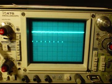
It is not a dessign nor contruction of the adapter. Is a Spectrum' problem, indeed!. The rubber keys hides this. The inner Basic editor reads the keyboard from time to time, each 20 milliseconds. If you press and release the key before this lap, the half-row has not been read yet. This behaviour recalled me when I was changing a genuine broken keyboard for switches (see section 'tips for solve membrane problems). If one key was pressed 10 times, I only got 6 or 7 characters in the screen, instead of 10 as expected. Here you are the oscilograme of signal which enables the reading: ease to see 8 pulses, one to each half-row.
Techical data: The reading of keyboard give a train of 8 pulses, 700 nanoseconds each, separates apart 16 microseconds beetween them. Time beetween trains of pulses is 20 milliseconds. Using the Basic editor, each program reads the keyboard using it's free will, usually faster, not periodical, not every half-row .
If I press simultaneously several keys, looks like the last ones doesn't work. Is it a damage or a fault?
Neither of both, really the problem is caused by PC keyboard. For dessign, there are a maximum number of keys that can be pushed at same time before a error arose. Typically are 5 or 6, depending on which keys be. Your only chance is to try another keyboard an cross your fingers. Anyhow, I've never found a program that needs more than 5 keys pushed at same time.
I've got an older keyboard, the one that have the function keys at left side and I want to use it with IMAR-3 interface. Are you planning include a project for XT keyboards?
No, there is a very big difference beetween XT and AT - PS/2 keyboards. I would needed to do all work again. If you've got an old XT, for sure doesn't work.
I'm a Fairlight fan , but it doesn't run. What can I do?
You have to use this POKE to solve this:
POKE 62470,24
¿Can I connect the IMAR-3 to the Spectrum PLUS 128K, +2 or +3?
No, it is designed for 48K and 48K+ only.
Why two modes, Normal and Edition?
Normal mode is just to play games and it doesn't implement any special funcion. Edition mode implement some special functions very usefull to editing programs. You can select mode with F12
Is it Freeware the software running inside the PIC?
Not really... is GreatGuyWare. That means, that in case you uses it, you have to send me an e-mail saying ' You are a great guy sharing you time and your work with the whole world, and in adition, you are not earning money. A true contributor'. This helps me to know if people really uses my hard work that I'm sharing here. In this way I'm stimulated to promote the birth of new projects like this one.
IF YOU HAVE NEW QUESTIONS ABOUT THIS MATTER, PLEASE E-MAIL ME AT droy@eresmas.com
24/4/2002 Begin the desing.
| imar3_sch_PDF_D.zip (New ! 5/9/2002) | Electronic schemme in PDF format |
| imar3_sch_D.zip (New ! 5/9/2002) | Electronic schemme in Eagle 4.0 format |
| Library for Eagle with the Spectrum slot connectors | |
| imar3_pcb_PDF_D.zip (New ! 5/9/2002) | PCB in PDF format |
| imar3_pcb_D.zip (New! 5/9/2002) | PCB in EAGLE format |
| imar3_Hex_V2.zip | File to program the PIC. Valid for PS/2 and AT keyboards: |
| Document to build a PIC programmer |
Thanks to Fernando G. Fonseca for his work translating this article
and for his friendship.
I share the information here without any warranty nor responsability for the damages it could cause to your computer.
What I can tell you is that "IT WORKS !!!" but .... up to you.